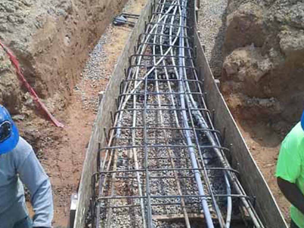

Also, the duct bank installer can use engineered backfill with these characteristics specifically designed.Īll heat created by an underground electrical cable must be dissipated through the adjacent soil. There are methods of analyzing the actual thermal characteristics of the soil, such as with a thermal property analyzer. One of the major components of this calculation is the RHO (see chart for typical RHO values for various types of fill). Because the main method of heat transfer within a duct bank is conduction, the air within the conduit will have less of an effect. In the air space within the conduit-the only area within a duct bank that does not conduct heat-convection occurs in lieu of conduction. The actual configuration of the conduits within a duct bank can be manipulated to reduce any potential derating, by placing the conduits with the most amount of heat dissipation at certain locations within the duct bank or separating conduits that will emanate the most heat.Īccording to Fourier’s law, heat flux is proportional to the ratio of temperature over space. If the RHO or load factor values are different from what is stated, then the tables do not apply. The NEC tables for underground duct banks are limited. The hand calculations become even more complex if cable in the duct bank are of different sizes. In addition, many of these calculations build on one another, so an error in one part of the calculation can result in a significant error in the final outcome. NEC Section 310-15(b) indicates calculations to determine actual rating of the conductors, and provides a formula that can be used under “engineering supervision.” But the formula typically is insufficient: It doesn’t include the effect of mutual heating between cables from other duct banks.įor distinctive duct bank configurations, a system designer must use the Neher McGrath calculation method, which involves many calculations and equations. This value is the reciprocal of thermal conductivity and is typically expressed in the units C-cm/watt.
#Concrete encased duct bank design code#
Thermal resistivity, as used in the National Electrical Code annex, indicates the heat transfer capability through a substance in the trench by conduction. The load factor in a data center would be significantly higher. The 41.6% load factor represents a standard commercial building. A customer uses 15,000 kWh with a maximum demand of 1,500 kW. Assume a one-day billing period for a total of 24 hours. Load factor, in percent, also can be derived by multiplying the kilowatt hours (kWh) in the period by 100 and dividing by the product of the maximum demand in kilowatts and the number of hours in the period.įor example, load factor = kWh in period/kW. Load factor is the ratio of the average load in kilowatts supplied during a designated period to the peak or maximum load in kilowatts taking place in that period. Additionally, various wire sizes can be used within the duct bank configurations. Any conceivable underground duct bank configuration can be input into the software.
#Concrete encased duct bank design software#
Electrical conductor heating calculations can be complicated, but there are software programs for determining the potential derating of feeder conductors in large electrical duct banks.

When electrical conductors overheat past their rated use, burning or degrading of normal insulation that protects conductors can precipitate a short circuit condition. RHO factor and the amount of the backfill material Horizontal and vertical space between conductors Number and size of conduits and conductorsĬonfiguration of the conduits and conductors When electrical duct banks with significant amounts of conduits and conductors are routed belowgrade, heating calculations are performed to determine if any conductor derating is required.


 0 kommentar(er)
